

REAL VIRTUALITY: The Use of Laser Stereolithography for the Construction of Accurate Molecular Models
by William J. Skawinski, Carol A. Venanzi, and Ana D. OfsievichDepartment of Chemical Engineering, Chemistry, and Environmental Science,
New Jersey Institute of TechnologyAbstract
For millennia humans have found it necessary to render images of visible objects and symbolic representations of abstract concepts for the purpose of bringing order to their complex world. This practice is particularly important in the evolution of science. With the continued development of computational and experimental methods which are capable of generating copious amounts of data, new techniques for representing this information in useful forms are needed. Though video displays can generate good quality representations of 3-D images, it is often useful to study real physical models of these virtual images. Additionally, scientists and students who are blind or visually disabled could benefit from such tactile models.The process of laser stereolithography, which automatically fabricates plastic models from designs created in certain CAD programs, has been applied to the production of accurate molecular models. The Stereolithography Apparatus (SLA) builds the models using a photosensitive liquid resin, resulting in hard plastic models which accurately represent the computed or experimental input structures, many of which are impossible to construct using standard techniques. Several examples are given to illustrate how the models can be used to interpret experimental structure-activity data for systems of biological importance or host-guest chemistry. This technique can also be applied to the fabrication of models representing a wide range of phenomena having specific spatial relationships.
Introduction
During recent years, virtual reality techniques have been developed to present us with computer generated images which can provide us with a perception of three dimensions. In our project, we take the virtual image and by using a rapid prototyping technique, fabricate real physical models of the virtual image, specifically molecular models. First, we will describe briefly, the need we humans have to create images of real and abstract concepts and then extend this to scientific visualization. Then we will describe the stereolithography process. Next, will be a description of the models we have produced and how they have been applied as tools in several research projects, and finally, a description of several future projects we are undertaking.Visualization
For a long time, humans seem to have had a need or desire to create images of specific objects of the natural world. In some ways this may be an attempt to gain a better understanding of our surroundings and by so doing, gain a degree of control over some part of our environment.The cave paintings found in Altamira and Lascaux may be as old as 17000 years. Significant effort was expended to produce these images. Artificial lighting had to be provided and scaffolding was required in some areas. The caves are generally not believed to have been used as dwellings and so were places possibly reserved for special purposes. We do not know why they were painted in these dark caves but speculation suggests either a religious or magical purpose. Perhaps the artists felt that creating the images of major prey animals would give them power over them. Some marks resembling projectile points in some images may even have been used to instruct hunters where to strike. These animals were real physical entities which could be observed easily in that environment, but humans have also demonstrated a need to depict visually, concepts which no one had ever seen.
In Michaelangelo's Last Judgment, behind the altar of the Sistine Chapel, he depicts his impression of the end of the world. The souls of the just receive their reward while those of the evil are condemned to a lurid array of imaginative tortures. To some degree this was an instructive image, at a time of limited literacy, exhorting people to be righteous.
There was also a need to visualize processes by which the physical universe came into being. Again, Michaelangelo, in his depiction of the Creation on the ceiling of the Sistine Chapel, shows the Genesis view of the creation of the universe and plants, animals and man. These were the predecessors of the Big Bang of Eddington and Hawking and evolutionary theories of Darwin and Leakey.
Scientific Visualization
As scientific thinking developed, the need for formal visualization techniques grew. It was necessary to be able to communicate increasingly complex ideas to a larger and more diverse audience.Descartes, who first unified algebra and geometry, provided a standard method of presenting data in ways which would be more informative. Our concern is specifically with the depiction of data on molecular structure in such a way as to give some insights into the nature of chemical processes, which in turn may allow us to control these processes, much like the magic of the Paleolithic artists may have been expected to give them control over their world.
Computer generated models of biologically important macromolecules on video displays can give scientists insights into many of their observed properties. The image provides insight into the overall structure of the molecule but specific distances and topology are difficult to perceive. Interactions of these macromolecules with smaller ligands such as drugs, hormones and vitamins are often dependent on specific structural features.
Besides structural relationships, it is also important to be able to represent the spatial distribution of other physical phenomena. In the case of these macromolecules, ligands interact through electrostatic forces distributed over the surfaces of the molecules. Excellent video images which represent the intensity of this potential as a spectrum of colors can show how two molecules can interact. You could say that this is a four dimensional image since the colors represent the intensity of the potential and are distributed through three spatial dimensions.
Modern Visualization Techniques
Today with the increasing power of supercomputers and long- range sensing devices, a vast amount of numeric data is being accumulated. Unfortunately much of this data is being stored for later use because the techniques for representing and evaluating these data are inadequate. An NSF sponsored report recommends the development of new methods for visualizing scientific data1.Currently, we depend on several techniques for representing molecular structures and associated physical properties but each has some limitations.
2-D representations are the simplest type but are inadequate for representing spatial relationships as the size and complexity of molecules increases. They are most useful as mnemonics for jogging our memories.
3-D video displays can produce excellent images but in order to gain some critical insights into the topology of the structure it may be necessary to change perspective frequently by rotating the image, which may lead to visual fatigue. Some systems may utilize special glasses to give the perception of depth but visual fatigue is also possible.
Virtual reality systems which can include video displays or holograms, improve spatial perception but are expensive and the images are not portable. As with any video display, you are tied to the computer if you want to view these images.
Tactile Models
Though video displays produce images which can be useful tools, they are of no use to those scientists and students who are blind or visually disabled. There are however, ways of getting tactile images of molecular structures. First, there are the standard molecular model kits. Because they are standardized they necessarily provide only a limited range of bond distances and angles. The range of atomic radii are also limited. As you attempt to construct models of larger systems the problem of accurately setting the torsional angles becomes more significant so that small errors in these parameters may result in a model which may not truly represent the computed or experimental data. In the November 1992 issue of Scientific American2 there appeared an article describing methods of visualizing biological macromolecules. Besides the usual video displays the article briefly mentioned a system of tactile feedback. This is probably related to the "data glove" which was originally worn by a computer user and allowed hand movements to be monitored by a computer allowing objects on the screen to be manipulated by hand, sort of like a highly evolved mouse. In order to provide users with additional sensory inputs to allow better manipulation, a system was added which produced physical resistance to motion in directions defined by the shape of the object on the screen. This gave the perception of actually "feeling" the object on the screen. But keep in mind that both physical models and the tactile feedback system were not designed for blind users. This demonstrates that the tactile sense is recognized as providing important insights into spatial relationships for sighted researchers and should not be ignored.Stereolithography
The concept of rapid prototyping includes several techniques which automatically fabricate physical models of images designed in CAD programs. The method is normally used by engineers and designers to make prototypes of their designs. The basic principle behind most rapid prototyping methods is the reduction of a problem in three variable dimensions to a problem in two variable and one constant dimension.SLA Hardware
The central component of the stereolithography apparatus is a cubic tank, approximately ten inches on a side. Within the tank is a computer controlled table or platform which moves vertically. The tank is filled with a photosensitive liquid polymer resin. At the start of the stereolithography process, the platform is raised to a level at which a thin layer of liquid resin lies above its surface. The computer then directs the output of a helium cadmium ultraviolet laser to trace out or draw the shape of the first or lower slice of the object designed in the CAD program. The interaction of the ultraviolet light with the resin cures the liquid forming a solid plastic material in the shape of the first slice. The table is then moved downward by a specified increment so that a thin layer of liquid now lies above this first slice. The laser now traces out the shape of the second slice again curing the liquid and simultaneously bonding this second slice to the first. The process is repeated until the entire object is fabricated slice by slice from bottom to top. The platform is then raised until the object emerges from the resin and excess liquid is allowed to drain. It is then placed in an ultraviolet oven for final curing after which it emerges as an accurate solid plastic model of the object designed in the CAD program.Software Considerations
Since the CAD programs have the ability to produce files for rapid prototyping, the image of the molecule must be created in a CAD program. The simplest representation of atoms is as spheres of specific radii while bonds are formed simply by the overlap of these spheres. Starting with data on the radii and cartesian coordinates of the atoms as obtained from quantum mechanical calculations or x-ray or neutron diffraction data, the sphere representing the first atom is drawn in the CAD program and located at the proper position in space. The sphere representing the second atom, bonded to the first, is then created and overlaps the first sphere. At this point, the program still recognizes these two spheres as separate objects which can still be moved independently so a command is issued to redefine the two overlapping spheres as a single object. This process is repeated for the remaining atoms in the molecule. For molecules consisting of four or five atoms data can be entered manually but for larger systems this is too time consuming and can lead to data entry errors. In order to prevent this we utilize a feature of the CAD program which allows a series of commands to be executed sequentially. This permits us to prepare the data in the form of a text file which can automatically be read into the program, automating the input process.We also utilize another useful feature of the CAD program. The cost of the resin is currently about $800 per gallon and so to reduce the cost we needed to make hollow models. You can cut various regions from a solid object in the CAD program manually but this is again time consuming and can result in errors. We use another input program which takes the same input file used to create the original molecule but reduces the atomic radii by several percent. This results in an image of a molecule with identical atomic coordinates but smaller radii. These two images are then superimposed and the smaller inner image is cut from the larger outer image resulting in a hollow model. Next, some holes are cut into this image to allow resin, trapped during the fabrication process, to escape. Because of the horizontal slicing process in some cases a slice may consist of several disconnected parts. For example, consider a lamp post consisting of a vertical post, a horizontal boom, and a lamp suspended from the end of the boom. If you slice this structure horizontally from bottom to top the first slice through the bottom of the lamp will not be connected to any other part of the structure during fabrication and thus cannot be built in this way. If the object cannot be oriented in such a way as to eliminate this problem, another technique has to be applied. A support structure can be fabricated beneath the lamp so that when the first, lower slice of the lamp is fabricated it will be supported. Before the first layer is fabricated there is a base layer made to connect all of the lower parts of the model. These temporary supports are removed after fabrication. The supports can either be designed manually or more efficiently by software which takes the file of the image, analyzes it and automatically designs any required supports. The object and supports are then merged into a single file for the next step. The final step of the file processing is the slicing of the image into the actual entities which will be fabricated. This is done by a Slice program which prepares the data for use by the stereolithography apparatus.
Unique Features
The unique features of this method include most importantly the accurate representation of data. All radii, bond distances, bond angles and torsional angles can be made precisely as determined by computational or experimental methods. The atomic radii which are after all a manifestation of some physical properties, can be chosen to suit the needs of the model. Initially we used published van der waals radii from the CRC Handbook but these resulted in atoms which overlapped to a large extent resulting in less distinct atoms. Any radii could be selected but we wanted to be sure that they represented some physical property. Our goal is not to make artistic displays but correct scientific models. We then switched to the published radii selected as a standard for CPK models. They are in many cases slightly smaller than the van der Waals radii and result in less overlap and more distinct atoms. Another unique feature is the ability to fabricate models at any scale. We have some striking examples of this. In general, this method allows a user to make a model to suit the needs of the particular application, whether in research or education.These models can represent transition state structures which can have unusual bond distances and angles. They can also be used to investigate complementary binding sites on proteins which will be described later. Also physical properties, such as electrostatic potential, can be mapped on the surfaces to depict their spatial distribution. Video images may use colors to represent values over the surface of a molecular structure while this technique can use surface features such as raised dots whose density on the surface or height can be made proportional to the value of the property.
Applications of Models
Our simplest application for these models was in the study of structure activity relationships of amino acids and several structural analogues with amino acid receptors in the channel catfish. The binding interaction of the amino acids have been shown by experimental and computational studies to be dependent on the size of the residue3. We constructed several models of the minimum energy conformations, using structural data obtained from ab initio molecular orbital calculations and published van der Waals radii. The models clearly showed that the space occupied by structures with similar binding characteristics were also similar.
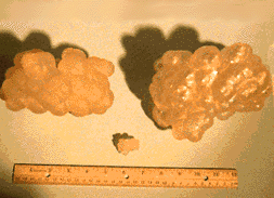
Cyclodextrins, carbohydrate macrocycles, have been studied as enzyme mimics. Beta cyclodextrin, which is composed of seven glucose units, for example, can accelerate the reaction rate of hydrolysis of phenyl esters relative to the rate in aqueous solution. Studies have suggested that nucleophilic attack on the carboxyl carbon might be carried out by either the 2' or 3' hydroxyl groups of beta-cyclodextrin. Extensive semiempirical studies and calculations incorporating solvent effects showed that attack by the 3' hydroxyl was energetically more favorable 4. Models were made of the neutron diffraction structure of beta- cyclodextrin and the calculated transition states for these two reaction paths. The models clearly show the arrangement of hydroxyl groups in the macrocycle and the position of the phenyl acetate guest within the cavity of the carbohydrate host. These models were made at a large enough scale to allow easy examination of the internal cavity.
Models of amino acid analogues. Top row from left: 1-amino-1-cyclopropane carboxylic acid (solid model, hollow model, hollow model). Bottom row from left: L-alanine, beta-chloro-L-alanine, L-serine, glycine.
Amiloride is a potent sodium channel blocker occasionally used as a diuretic drug. It interacts with the epithelial sodium ion channel to block the flow of sodium ions. Several structural analogues of amiloride exhibit similar properties though quantum mechanical molecular orbital calculations have shown these analogues to be considerably non-planar, unlike the planar amiloride 5.

Solid model of ß-cyclodextrin (left), hollow model of ß-cyclodextrin transition state with phenyl acetate (right), small scale hollow model of ß-cyclodextrin transition state with phenyl acetate (middle); top view.
Solid model of ß-cyclodextrin (left), hollow model of ß-cyclodextrin transition state with phenyl acetate (right), small scale hollow model of ß-cyclodextrin transition state with phenyl acetate (middle); side view.
A model was made of a region of space complementary to amiloride, essentially an impression of the planar molecule. This serves as a first approximation of the geometric requirements for interaction between amiloride and the appropriate site on the sodium channel protein. Experimental studies have shown that the spatial arrangement of certain parts of this molecule are essential for biological activity. Models were made of the most stable conformations of the analogues and the interaction of these structures with the complementary site model were examined. It was observed that the important areas on the complementary site model could readily interact with the important parts of the analogue models though their shapes were quite different than that of amiloride.
As a tool for communication between blind and sighted scientists, these models proved to be an instant success6. They eliminate the need for cumbersome and inconsistent verbal descriptions or standard models particularly in depicting critical spatial relationships as in the beta-cyclodextrin transition states and the amiloride interactions with the model of the complementary site. They allow more effective discussions between blind and sighted researchers.
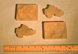
Top row from left: Amiloride in complementary site, analogue 18. Bottom row from left: analogue 19, complementary site.
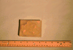
Amiloride in complementary site.
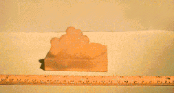
Analogue 19 in complementary site (side view).
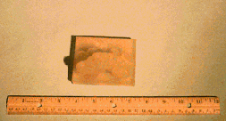
Analogue 19 in complementary site (top view).
Besides being used specifically in the education of blind students these models should be useful in any educational situation including blind and or sighted students. We have already received inquiries from a group which produces chemistry education materials.
Future Projects
As these early examples have shown, these models can significantly contribute to research projects concerned with structural questions 7. We plan to refine and extend these techniques to allow a much wider range of phenomena to be modeled.We are currently in the process of constructing a model of a protein molecule from x-ray data. Though this is a scale up of the procedures we used for the smaller molecules, the greater number of atoms and larger physical size produce significant new problems. Since we are limited by the size of the tank of the stereolithography apparatus to building objects which can fit within a 10 inch cube, the scale of the protein model will have to be reduced if it is to be built in a single step. Alternatively, if a larger scale is required, the model will have to be cut into manageable segments within the CAD program and each fabricated separately and the complete model assembled afterwards. The many features of the CAD program can insure that this could be done precisely. For example, when the image is cut, tabs, holes and keys can be designed into the interfaces between the segments to insure accurate assembly.
Our first attempt to model physical properties will be to fabricate a meaningful map of molecular electrostatic potentials. There are several approaches being considered. One is to employ surface features on the molecule whose density or height is proportional to the potential at that point in space. Another is to model a closed surface which represents the region of space at which the potential has a specific value. Several models can be made representing different values of the potential.
In some cases the spatial relationships of physical properties can be expressed mathematically and surfaces can be generated in the CAD program. In addition, variables other than spatial coordinates can be used to represent any manner of mathematical relationships. These might then be modeled by stereolithography 8. Maxwell, in his work on electricity and magnetism found it useful to produce clay models of such surfaces1.
Keeping in mind that molecular structures are not static and undergo a number of internal motions, we plan to model some of these dynamic processes. The CAD program allows the formation of a solid image by moving an object through space. This could represent the space occupied by atoms as they vibrate or rotate and could better define the steric requirements for chemical reactions. We plan to use the results of molecular dynamics calculations to make such models to examine their value in considering steric questions.
Conclusions
The first series of models we have constructed have proven to be immediately useful to blind and sighted researchers and students. The importance of understanding molecular structure in detail is necessary for the understanding of mechanisms of biochemical systems as well as properties of new materials. A greater understanding of these structures can be useful in designing new molecular systems with specific properties. The accuracy and relative ease of fabrication of these models can provide a valuable new tool in a number of areas of research.
Dr. Venanzi and Dr. Skawinski wish to thank the National Science Foundation for funding the stereolithography work described here.
References
For further information, contact the authors: skawinski@tesla.njit.edu or ven001@tesla.njit.edu
Department of Chemical Engineering, Chemistry, and Environmental Science,
New Jersey Institute of Technology, 323 King Blvd., Newark, NJ 07102
Copyright © 1996, Nanothinc. All Rights Reserved